Seismograph in geophysics
The first seismographs were built in the late 19th century were a mechanical synthesis of sorts - a seismometer rigged up to transfer its motions to some kind of timekeeping and recording device. Records, which became known as seismograms, were made continuously, by a pen tracing ink lines on paper, or a stylus etching smoked paper, with time "ticks" marked periodically to provide temporal reference points. See figure (3 and 4).
What is a Seismograph?
Seismograph Is the sensor device used to amplify and detect ground vibrations. Sometimes the word Seismometer is used to infer the same device.
Seismographs basically consist of two (2) parts which are, 1. A seismometer: This is a sensor of ground motion 2. A seismic recording system.
Basic Working Principle
How does a seismograph work?
Principle used by the seismometers, is that It works by "Inertia principle" . The most common is by using a mass suspended by a spring. This mass follows the motion of the ground (although in the opposite direction). This motion can then be converted to an electric current by having the mass be an (electro-) magnet inside the core of a coil, i.e. the change in magnetic flux induces an electric current in the coil.
Measures can be taken so that the mass follows the motion of the ground rather than oscillating with its own natural frequency. This can be achieved by damping its motion either mechanically, or electromagnetically, using additional coils. The electrical signal can then be magnified and digitized.
.gif)
In simple words
A seismograph works by using a suspended needle attached to a large mass that 'draws' on a piece of paper. When the ground moves, along with the paper, the suspended needle doesn't move, which results in the needle drawing zig zags on the paper corresponding to how the ground moves.
SEISMOGRAM
Seismogram is the visible record of converted amplified ground motion displayed on a seismometer.
For most of the last century, seismograms were recorded on sheet of paper, either with ink or photographically.
However when describe the seismogram can either recorded in two (2) formats.
Analog Records
These records can be read just like a book - from top-to-bottom and left-to-right, see figure 2.
 Figure 2: Seismogram displays vertical component of seismic waves (Lay and Wallace, 1995).
Digital Records
These records are "sampled" at an even time interval, depends on the type of seismic instrument and the interest of the people who deploy the seismometer (connected with Nyquist frequency), for a range of times (connected with spectral resolution).
However today, most seismic data are recorded in this format (digitally), which facilitates quick interpretations of the signals using computers. See figure below.

TYPES OF SEISMOMETER
There are two (2) basic types of seismic sensors based on their primary working principles.
1. Inertial Seismometers
These measure ground motion relative to an inertial reference (a suspended mass). An inertial seismometer basically measures the inertial force acting on the seismic mass in an accelerated local frame of reference.
It depends on its two functional subunits which are the mechanical suspension and the displacement or velocity transducer.The suspension converts the inertial force into a displacements of the mass, and the transducer converts this into an electric signal. Neither one of these conversions is inherently precise.
Since suspended mass does not represent a perfect inertial reference always inertial seismometers have an inherently frequency dependent response (transfer function of a forced pendulum) that must be taken into account when the ground motion is restored from the recorded signal.
When the ground motion is slow, the mass will begin to follow it, and the output signal for a given ground displacement will therefore diminish. The mechanical system forms a high-pass filter for the ground displacement. Recorders, on the other hand, normally have a constant gain up to some upper cutoff frequency, and contribute only a scale factor to the overall response.
N.B: A sensitive seismometer must have a suspension with a small restoring force so that small accelerations produce noticeable displacements of the seismic mass. Then, of course, larger seismic signals or environmental disturbances produce large displacements that change the geometry of the spring and destroy the linear relationship between displacement and force.
When the restoring force is diminished, undesired effects such as hysteresis and viscous behaviour retain their absolute magnitudes and thus become relatively larger. Finally, it is difficult to build linear transducers with a large range. A passive seismic sensor therefore cannot be optimized for sensitivity and precision at the same time.
2. Strainmeters (extensometers)
These measure the motion of one point of the ground relative to another. The wavelength of seismic waves is so large that the differential motion of the ground within a vault is normally much smaller than the motion relative to an inertial reference.
Strainmeters are therefore generally less sensitive to earthquake signals. However, at very low frequencies it becomes increasingly difficult to maintain an inertial reference, and for the observation of low-order free oscillations of the earth and tidal signals, strainmeters may outperform inertial seismometers.
Depending on modes of operation
Horizontal Seismometer
This record the horizontal vibration of the ground caused by horizontal component of seismic waves.
As in the “garden-gate” pendulum the mass moves in a nearly horizontal plane around a nearly vertical axis. The restoring force is now g(sinα) where α is the angle between the vertical and the rotation axis, see figure 3
To obtain a natural frequency of 0.05 Hz with a pendulum length of 20 cm will require a tilt of 0.1 degree. Making the angle smaller makes the instrument very sensitive to small tilt changes. The “garden-gate” was one of the earliest designs for long period horizontal seismometers, is still in use but no longer produced.
Principle of the garden gate pendulum, the tilt angle is exaggerated. The figure also shows how long a string pendulum must be to have the same natural frequency.
In order to obtain high sensitivity to low frequency seismic waves, we need a low natural frequency. With a standard mass spring sensor, a large mass combined with a soft spring will give a low frequency, but this arrangement is limited by the mechanical properties (e.g. to get a period of 20 s, a length of 100 m is needed!).
For both the pendulum and the spring system, if the restoring force is small, the natural frequency will be small. The solutions is to use astatic suspensions where the restoring force (gravity) is very small and, theoretically, any natural frequency can be obtained.

Figure 3: Horizontal seismometer (Lowrie, 2007)
Vertical Seismometer
This record the vertical vibration of the ground caused by vertical component of seismic waves.
An astatic spring geometry for vertical seismometers was invented by LaCoste (1934). The mass is in neutral equilibrium when three conditions are met: the spring is prestressed to zero length (i.e. the spring force is proportional to the total length of the spring), its end points are seen under a right angle from the hinge (pivot), and the mass is balanced in the horizontal position of the boom

Figure 4: Vertical seismometer (Lowrie, 2007)
Mechanical Seismometer
This seismometer has the stylus attached to the mass etched a record directly onto a rotating drum covered with smoked paper.
The only damping was due to stylus friction and mechanical friction, and the restoring force acting on the mass was simply gravity. Early mechanical instrument which was the horizontal pendulum developed in 1905 by Bosch-Omori. See figure 5.
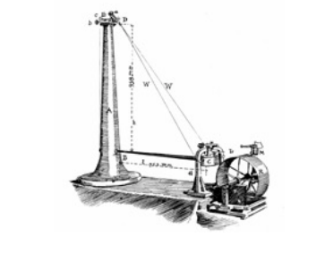
Figure 5: Mechanical seismometer developed by Bosch-Omori (1905)
Torsional Seismometer
The seismometer motion due to earthquake is generated from the torsional (rotational) motion of a small inertial mass affixed to a thin wire under high tension. However the damping of the torsional motion accomplished using magnets.
Seismograms drawn not with a stylus or needle, but with a beam of light reflected onto photosensitive paper from off of a mirror on the inertial mass.
The basic of this seismometer design was developed in southern California by Harry O. Wood and J.A. Anderson, who invented the "torsion seismometer" in 1922. This lead to this seismometer named as "The Wood-Anderson torsion seismometer".

Figure 6: The Wood-Anderson torsion seismometer
Electromagnetic Seismometer
The seismometer has a mounted coil of wire on the pendulum and suspended both between the poles of a magnet fixed to the earth. During an earthquake, the magnetic field was moved around a coil generating electrical current. Because of this the recorder could now be separated from the seismograph.
The early electromagnetic seismometer was designed by Boris Galitzin in 1906.

Figure 7 (a): Basic working components of electromagnetic seismometer

Figure 7 (b): The electromagnetic seismometer designed by Boris Galitzin (1906)

Force – Balance (retroaction) Accelerometer
The seismic mass and adjusts the force so that the mass returns to its center position. Due to unavoidable delays in the feedback loop, servo systems have a limited bandwidth; however at frequencies where they are effective, they force the mass to move with the ground by generating a feedback force strictly proportional to ground acceleration.
When the force is proportional to the current in the transducer, then the current, the voltage across the feedback resistor R, and the output voltage are all proportional to ground acceleration.
We have thus converted the acceleration into an electric signal without relying on the mechanical precision of the spring. See figure 8

Figure 8: Layout of Force – Balance (retroaction) Accelerometer
The suspension still serves as a detector but not as a converter, and may now be optimized for sensitivity without giving up precision.
This is widely used for earthquake strong-motion recording.
N.B: These days there are modern seismometers which combined electromagnetic and mechanical operation principles known as electromechanical seismometers. However the basic idea behind measuring ground movement can be illustrated using a simpler physical system that is actually quite similar to some of the earliest seismograph systems.
Thanks for your time! Regarding the basics about this device.
References
Bolt, B. A., (1993). Earthquakes, W.H. Freeman, N.Y., 331 pp.
Bolt, B.A., (1993). Earthquakes and Geological Discovery, Scientific American, NY 229 pp.
SHARE! With your friends and colleagues!
Do you want to support the effort? via >"Support by Donate "<
Follow this blog on WhatsApp group to gain more benefits.
➔ New eBook! New eBook! Launched and discounted.
Get quick insight on geophysics techniques and concepts in simplified comparison manner!
➔ Comparative Geophysics eBook.
It is time to get this ebook now! Read it and leave a honest review.


Comments
Post a Comment